| Cat.
Ref.
|
HEM4 |
HEM6 |
| Vessel
sizes -------------------------------------
litre |
20 |
50,
100 & 200 |
| Heat
transfer area-------------------------------------m2
(ft2) |
0.15
(1.5) |
0.5
(5) |
| Water
throughput at 2.1 kg/cm2----------
1/h (UKgal/h) |
1364
(300) |
1364
(300) |
| Max
steam pressure-----------------------kg/cm2
(lbf/in2) |
2.7
(40) |
2.7
(40) |
| Vessel
opening -----------------------mm
(in) |
100
(4) |
330
(13) |
| --------------------------------------------------------
DN |
40
(1.5) |
40
(1.5) |
| --------------------------------------------------------
DN1 |
25
(1) |
25
(1) |
| --------------------------------------------------------
DN2
|
130
(9) |
230
(9) |
| --------------------------------------------------------
L |
255
(10) |
330
(13) |
| --------------------------------------------------------
L1 |
--- |
--- |
|
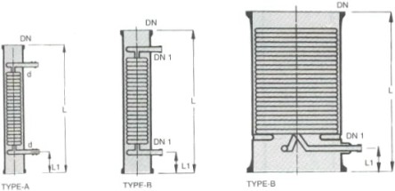
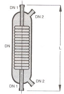
Shell
and tube heat exchangers provide a versatile
alternative to the coil-type heat exchangers.
These can be used as condensers, but are
equally suitable for heat transfer between
two liquids or gases.
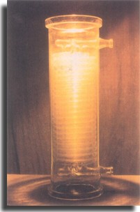
These
shell and tube heat exchangers are of
modular construction. They comprise
the following individual elements: tubular
shell, headers, tube plates, heat exchange
tubes and baffles. Sealing of the individual
tubes in the tube plate is of particular
importance. The threaded PTFE bushes
and PTFE sealing rings provide a seal
of the highest integrity between the
different materials.
Shell
& Tube heat exchangers offer large
surface area in combination with efficient
heat transfer and compactness. These are
widely used in industries for various
duties like cooling, heating, condensation,
evaporation etc. |
| Salient
Features : |
| |
Universal
corrosion resistance an excellent
alternative to expensive MOCs like
graphite, hastelloy, copper titanium,
tantalum and other exotic metals. |
| |
Excellent
heat transfer as fouling does not
occur on smooth glass surfaces. |
| |
Flexibility
of installation vertical/horizontal. |
| |
Easy
replacement of tubes for repair
and cleaning. |
| |
Available
in wide range of HTAs. |
| |
Ease
of installation due to light weight. |
| |
Economical. |
| |
Suitable
for applications where large HTAs
are required in limited space. |
|
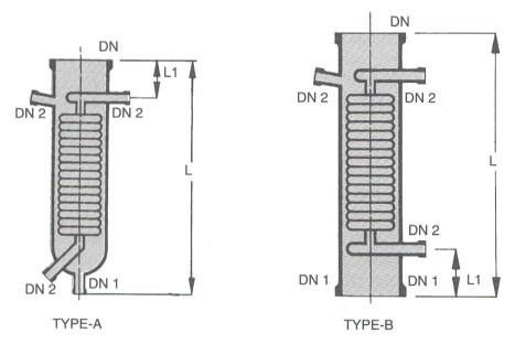
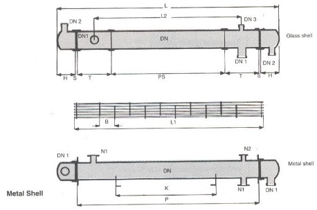
| Construction
Features : |
The
glass tubes are sealed individually into
PTFE tube sheet with special PTFE sockets
and packing. This unique ferrule type
sealing arrangement permits easy replacement
and cleaning of tubes. Baffles on shell
side ensure improved heat transfer by
increased turbulance. Further details
of construction an be seen in the diagram. |
| Type
: |
| Three
basic versions are available : |
Material
Of Construction |
| Model
|
Shell |
Tube |
Header |
Duty |
| RGG |
Glass |
Glass |
Glass |
For
heat transfer between two aggressive
media. |
| RGM |
Glass |
Glass |
Steel/FRP |
For
heat transfer between aggressive
media in shell & non-aggressive
media in tubes. |
| RMG |
Steel/FRP |
Glass |
Glass |
For
heat transfer between aggressive
media in tubes & non-aggressive
media in shell. |
|
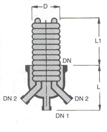
| Dimensional
Specifications : |
|
| Cat.
Ref. RGG/RMG
|
6/3 |
6/4 |
6/5 |
6/6 |
9/6 |
9/8 |
9/10 |
9/12 |
12/12 |
12/16 |
12/21 |
12/25 |
| Area
(m2)
|
3 |
4 |
5 |
6 |
6 |
8 |
10 |
12 |
12 |
16 |
21 |
25 |
| DN |
150 |
225 |
300 |
| DN1 |
80 |
100 |
150 |
| DN2 |
50 |
80 |
80 |
| DN3 |
25 |
40 |
40 |
| DN4 |
50 |
50 |
50 |
| H1 |
175 |
250 |
300 |
| H2 |
150 |
200 |
250 |
| L |
2500 |
3100 |
3700 |
4300 |
2620 |
3220 |
3820 |
4520 |
2550 |
3150 |
3950 |
4550 |
| L1 |
1900 |
2500 |
3100 |
3700 |
1900 |
2500 |
3100 |
3800 |
1800 |
2400 |
3200 |
3800 |
| L2 |
150 |
150 |
150 |
150 |
225 |
225 |
225 |
225 |
225 |
225 |
225 |
225 |
| L3 |
1600 |
2200 |
2800 |
3400 |
1450 |
2050 |
2650 |
3350 |
1350 |
1950 |
2750 |
3350 |
| L4 |
250 |
250 |
250 |
250 |
300 |
300 |
300 |
300 |
300 |
300 |
300 |
300 |
| L5 |
125 |
125 |
125 |
125 |
175 |
175 |
175 |
175 |
175 |
175 |
175 |
175 |
| L6 |
1980 |
2580 |
3180 |
3780 |
2000 |
2600 |
3200 |
3900 |
1930 |
2530 |
3330 |
3930 |
| T |
50 |
60 |
75 |
| No.
of Tubes |
No.
of Baffles |
11 |
15 |
| |
|
|
|
|
| Range
Of Applications : |
Permissible
temperature range for both shell &
tube sides - 400
C to 1500
C.
Maximum permissible temperature difference
between shell & tube sides = 1200
C.
All sizes & modes are suitable for
full vacuum on both side. Maximum limiting
pressures are tabulated here below : |
| |
|
Maximum
Permissible Pressure Range, Kg/cm2(g) |
| Model
|
Side |
150DN |
225DN |
300DN |
| RGG |
Shell
Tube |
2.0
2.0 |
1.0
1.0 |
1.0
1.0 |
| RGM |
Shell
Tube |
2.0
3.5 |
1.0
3.5 |
1.0
3.5 |
| RMG |
Shell
Tube |
3.5
2.0 |
3.5
1.0 |
3.5
1.0 |
|
The
above ranges of applications are admissible
limiting values. In actual practice we
can recommend the right selection on the
basis of prevalent temperature –
pressure parameters. |
| Performance
& Design Data : |
The
particular advantage of shell & tube
heat exchanger is high heat transfer performance.
The relation between heat transfer and
velocity of flow can be easily seen in
the diagram. On receipt of the operating
data from client the most favourable shell
and tube heat exchanger is selected. This
accurate design combined with most reliable
quality assurance ensures economy and
operational reliability for the user.
For approximate sizing some typical heat
transfer coefficients are given here below
: |
| |
|
Overall
Heat Transfer Coefficient (U-Values)
|
| Model
|
Use |
kcl/m2hrk |
W/m2k |
| Steam
water |
condensation |
350-550 |
410-640 |
| Water-water |
cooling |
250-350 |
290-410s |
| Water-Air |
cooling |
30-60 |
35-70 |
|